When the Interface Looks Clean: How Customer Policing Causes Invisible Packet Loss
Clean interfaces don’t always mean clean service. This lab shows how customer-side policing silently discards traffic, creating invisible packet loss without provider-side errors or drops.

When I started this lab, I knew I wanted to test packet loss — specifically how customer-side policing might cause it, and whether it would show up as output drops on the provider router.
We made real progress: we proved that customer policing can silently discard packets without causing any visible errors, congestion, or output drops on the PE side.
There's still more testing ahead — especially pushing traffic harder, forcing visible output drops, and exploring shaping and CoS queue behaviors.
This was just Phase 1. Here's how it unfolded.
🎯 Introduction
You're monitoring your Juniper PE router and everything looks clean:
Output errors: 0, Drops: 0No errors. No congestion. No alarms.
Yet the customer is calling your NOC, complaining: "We're experiencing packet loss, calls are dropping, our applications are slow."
You check again — the interfaces look perfect.
So where is the problem?
This is a common and frustrating scenario in service provider operations. Service-impacting loss can occur even when all provider equipment looks healthy.
One of the most overlooked causes? Customer-side policing and shaping.
- Policing: Enforces a hard rate limit by discarding packets that exceed a specified bandwidth.
- Shaping: Smooths traffic to a certain rate, buffering bursts instead of discarding immediately.
In this lab, we found specifically on customer ingress policing — where a customer's router silently discards any traffic exceeding a configured limit. No alarms. No output drops. No easy clues for the provider.
We built a full EVE-NG lab to simulate this:
- Sending traffic across a clean service provider core
- Applying a strict ingress policer on the customer's CE router
- Verifying that traffic was being discarded at the customer edge, not within the provider network
Our goal was not just to create packet loss, but to understand how loss can exist even when interfaces are clean — and to see how customer configurations can mask the true cause. I also wanted to see what the real causes for the incrementing Output Drops on the provider routers, but as you can see we didn't get to simulate that yet.
Next, in Phase 2, we will push the limits even harder:
- Attempting to generate visible output drops under more extreme conditions
- Testing with traffic shaping instead of pure policing
- Analyzing Class of Service (CoS) queues and real output queue congestion behavior
Understanding this distinction now prepares us for deeper, more advanced troubleshooting in future phases.
Now, let's do some tests.
🧪 Lab: Generate Traffic Across the Core
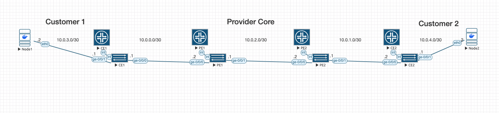
🔧 Topology
[CE1] —— [PE1] —— [PE2] —— [CE2]
- PE1 / PE2: Provider Edge routers (Juniper vMX)
- CE1 / CE2: Customer Edge routers (Juniper vMX)
🎯 Lab Goals
- Apply a strict ingress policer on CE2
- Send high-rate UDP traffic from CE1 to CE2
- Watch
output dropsincrement on PE2’s egress interface
🔌 Interface/Port Mapping Summary
| Device | Interface | IP Address | Description |
|---|---|---|---|
| CE1 | ge-0/0/0 | 10.0.0.1/30 | Connected to PE1 (ge-0/0/0) |
| PE1 | ge-0/0/0 | 10.0.0.2/30 | Connected to CE1 |
| PE1 | ge-0/0/1 | 10.0.2.1/30 | Connected to PE2 (ge-0/0/0) |
| PE2 | ge-0/0/0 | 10.0.2.2/30 | Connected to PE1 |
| PE2 | ge-0/0/1 | 10.0.1.1/30 | Connected to CE2 (ge-0/0/0) |
| CE2 | ge-0/0/0 | 10.0.1.2/30 | Connected to PE2 |
⚙️ Configurations
🔹 CE1
Configure the hostname
Configure the CE1 interface connected to PE1 with a /30 IP
Create OSPF instance to PE1
Create plain text password for root authentication
set system host-name CE1
set interfaces ge-0/0/0 unit 0 family inet address 10.0.0.1/30
set protocols ospf area 0.0.0.0 interface ge-0/0/0
set system root-authentication plain-text-password
[ENTER NEW PASSWORD] 2x
commit
🔹 PE1
Configure the hostname
Configure interface facing CE1 and PE2
Create OSPF instances to CE1 and PE2
Create plain text password for root authentication
set system host-name PE1
set interfaces ge-0/0/0 unit 0 family inet address 10.0.0.2/30
set interfaces ge-0/0/1 unit 0 family inet address 10.0.2.1/30
set protocols ospf area 0.0.0.0 interface ge-0/0/0
set protocols ospf area 0.0.0.0 interface ge-0/0/1
set system root-authentication plain-text-password
[ENTER NEW PASSWORD] 2x
commit
🔹 PE2
Configure the hostname
Interface facing PE1 and CE2
Create OSPF instances to PE1 and CE2
Create plain text password for root authentication
set system host-name PE2
set interfaces ge-0/0/0 unit 0 family inet address 10.0.2.2/30
set interfaces ge-0/0/1 unit 0 family inet address 10.0.1.1/30
set protocols ospf area 0.0.0.0 interface ge-0/0/0
set protocols ospf area 0.0.0.0 interface ge-0/0/1
set system root-authentication plain-text-password
[ENTER NEW PASSWORD] 2x
commit
🔹 CE2 (with Ingress Policing)
Configure the hostname
Configure CE2 interface toward PE2
Create a policer that drops traffic exceeding 5 Mbps
Apply policer to all traffic using a filter
Attach filter to ingress interface
Create OSPF instance to PE2
Create plain text password for root authentication
set system host-name CE2
set interfaces ge-0/0/0 unit 0 family inet address 10.0.1.2/30
set firewall policer TEST-POLICER if-exceeding bandwidth-limit 5m
set firewall policer TEST-POLICER if-exceeding burst-size-limit 10k
set firewall policer TEST-POLICER then discard
set firewall family inet filter DROP-TRAFFIC term 1 then policer TEST-POLICER
set firewall family inet filter DROP-TRAFFIC term 1 then accept
set interfaces ge-0/0/0 unit 0 family inet filter input DROP-TRAFFIC
set protocols ospf area 0.0.0.0 interface ge-0/0/0
set system root-authentication plain-text-password
[ENTER NEW PASSWORD] 2x
commit
🚀 Test and Observe
To prove that customer-side policing (not provider congestion) causes output drops — we set up a real-world simulation using two embeded Linux nodes in EVE-NG.
🛠️ Lab Preparation
- Add the Docker Linux CLI Nodes to your EVE-NG topology.
• Connect one node to CE1'sge-0/0/1interface and one node to CE2'sge-0/0/1 - Configure CE1 (
ge-0/0/1) to Connect to its Linux Node
Enter configuration mode on CE1:
configureAdd a new IP for the Node1 connection:
set interfaces ge-0/0/1 unit 0 family inet address 10.0.3.1/30
✅ This assigns 10.0.3.1/30 to CE1’s ge-0/0/1 port.
We can also set ge-0/0/0 to passive since we don't need OSPF on Node1.
set protocols ospf area 0.0.0.0 interface ge-0/0/1 passive
commit
It doesn't really make a difference one way or another for this lab, but it's best practice, so we'll do it.
- Configure CE2 (
ge-0/0/1) to Connect to its Linux Node
Enter configuration mode on CE2:
configureAdd a new IP for the Node2 connection:
set interfaces ge-0/0/1 unit 0 family inet address 10.0.4.1/30
✅ This assigns 10.0.4.1/30 to CE2’s ge-0/0/1 port.
We'll also set it to passive, just because:
set protocols ospf area 0.0.0.0 interface ge-0/0/1 passive
commit- Configure the Nodes
From the console of the Node1:
# Assign correct IP in the new subnet
ip addr add 10.0.3.2/30 dev eth0

# Bring up the interface
ip link set eth0 up

# Set default route pointing to CE1
ip route add default via 10.0.3.1
✅ Now the node is properly linked to CE1.
Lets configure Node2 now:
ip addr add 10.0.4.2/30 dev eth0
ip link set eth0 up
ip route add default via 10.0.4.1
✅ Now this node is properly linked to CE2.
Let's ping from node to node to test connectivity:
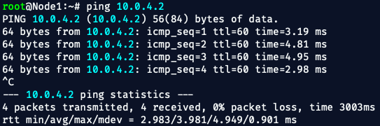
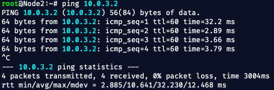
💥 Easy-Peasy!!
Now let's move to the next phase —
Generating traffic and proving the output drops based on policing at CE2!
🧪 Next Step: Traffic Testing to Prove Output Drops
Here’s exactly what we will do:
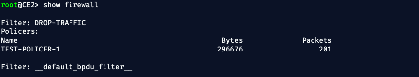
1. ✅ Confirm CE2 Ingress Policing is Correct
On CE2, confirm that the policer is still in place, attached to the correct interface:
show configuration firewallYou should see something like:
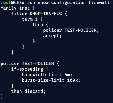
And it should be applied inbound on CE2's ge-0/0/0:
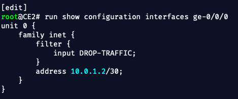
✅ Confirmed filter applied on input.
2. 🚀 Launch High-Rate UDP Traffic from Docker Linux CLI Node
From Node2, start the iperf3 server:
iperf3 -sFrom Node1:
iperf3 -c 10.0.4.2 -u -b 50M -t 60
This sends real IP UDP traffic across the core toward CE2.
🧠 What This Proved
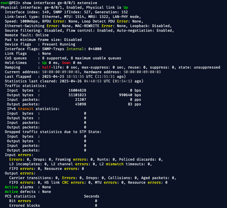
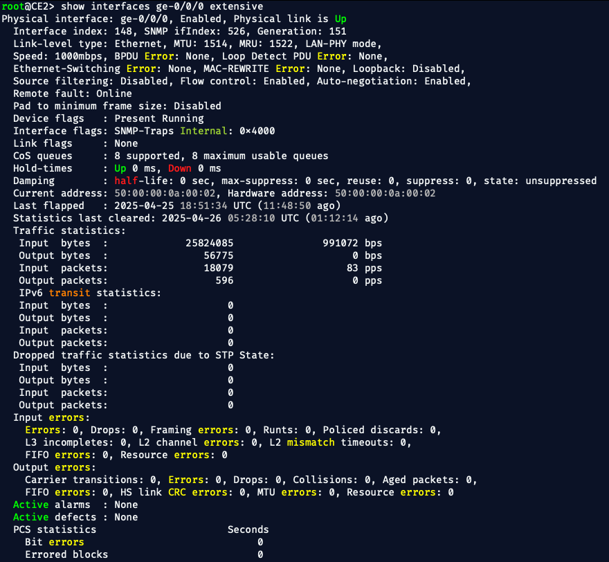
✅ Despite the PE router showing no congestion, no errors, and no output drops, service-impacting packet loss occurred at the customer edge.
✅ The packet loss was solely due to customer ingress policing, not a provider network fault.
✅ The service provider had no direct counters or alarms to detect this — only customer device inspection revealed the truth.
In a real service provider network, customer-side ingress policing or shaping may silently discard excess traffic, without causing visible output drops, congestion, or alarms on the provider’s PE router.
Engineers must recognize that service-impacting loss can occur even when all interface counters look clean — albeit due to customer-side configurations such as ingress policing or shaping policies.
This reinforces the need for end-to-end visibility, proactive testing, and thorough customer-side configuration review when troubleshooting unexplained packet loss or application performance issues.
💡 Conclusion
This lab clearly shows that:
- Customer-side policing can silently degrade service.
- No alarms, no output drops, no congestion signs may exist at the PE router.
- The true root cause lies in customer device configurations.
In Phase 2, we will continue pushing the limits:
- Forcing more traffic into queues
- Testing shaping vs. policing behaviors
- Analyzing CoS (Class of Service) queues under load
Stay sharp. Trust, but verify — even when the interfaces look clean.
Leave a Subscribe - Leave a comment or hit me up on LinkedIn
✌️OUT!
-Bryan