🧠Phase 4 – Ring Around the Backbone: Simulating a Protected Transport Core
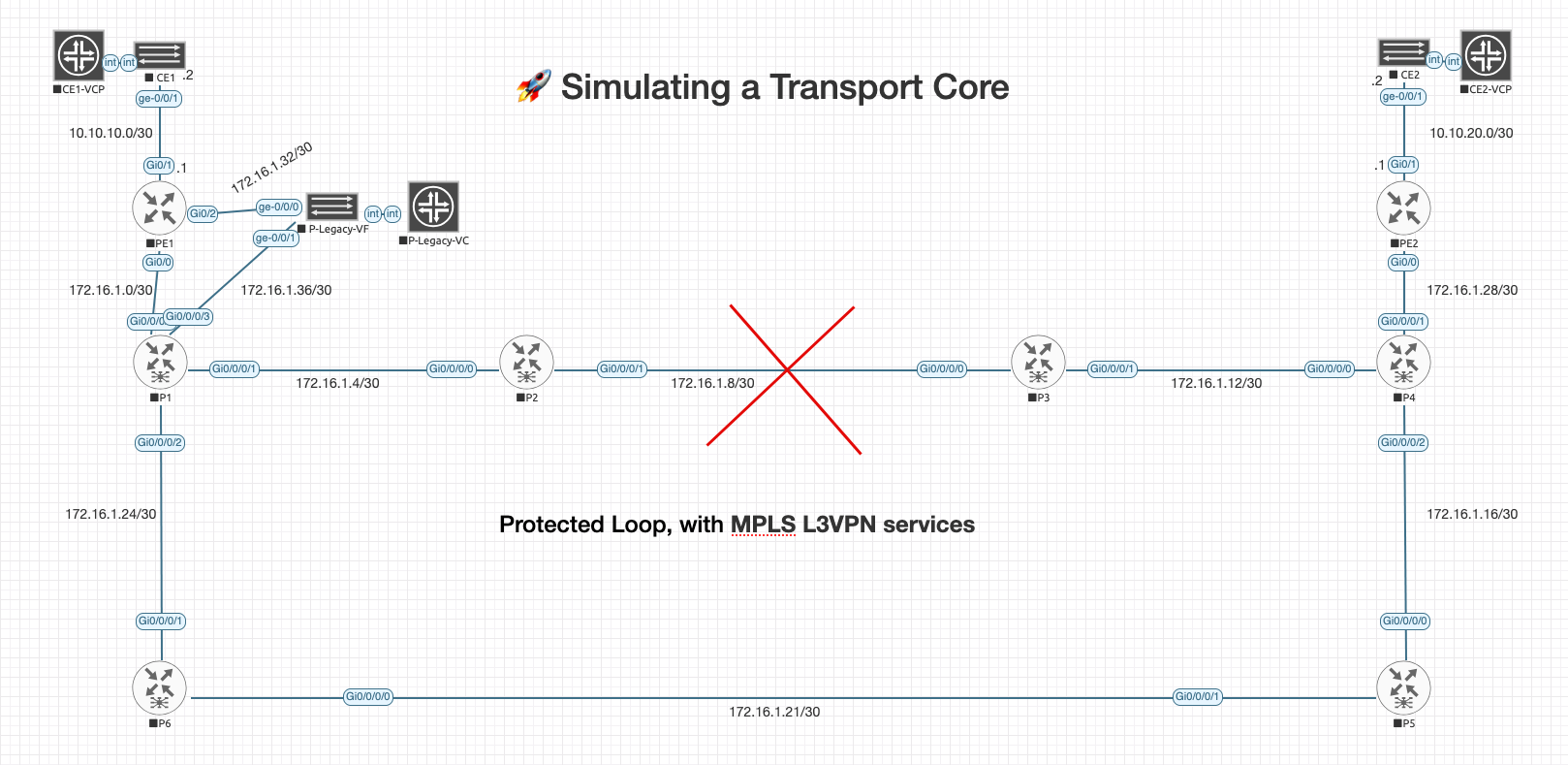
In Phase 4, I expanded the MPLS lab into a fully redundant core ring, enabling end-to-end VPN reachability and real-world fault tolerance testing.

➡️ Missed the last Phase? Start with Phase 3: Delivering Services with MPLS L3VPN
I got a good idea!— maybe it is, maybe it isn’t — Trying to wrap your head around how service provider networks might handle redundancy at the transport layer?Well, I really wanted to incorporate that but, I am not too familiar with any open-source images or anything outside of specific vendor training portals, where I could simulate Ciena's, Fujitsu, Nokia, Etc.
So, the next best thing. Making an MPLS core into a full redundant transport ring. I’m using six core Cisco IOS-XRv routers
(P1–P6) forming a protected loop, with MPLS L3VPN services still running end-to-end between Customer Edge routers.
Now to be clear — I know actual transport and transmission gear typically lives at Layer 1 and Layer 2. Think: DWDM, SONET/SDH, Ethernet Private Line (EPL), GFP, or circuit emulation over packet. Those services are delivered by devices that I can't simulating here or at least I haven't seen how yet.
What this lab does simulate is the resiliency and ring behavior that transport gear helps facilitate. We're using Layer 3 tools like OSPF, LDP, and MPLS to push VPN traffic around a fully redundant ring. It's not Ciena — but it can still be used to help understand the flow. For now, this feels like a solid plan for Phase 4.
We’re keeping everything from Phase 3:
- 🔁 MPLS LDP across the core
- 🔐 VRF Customer-A for VPN separation
- 🧠 iBGP VPNv4 between PE1 and PE2
- 🎯 Static routing between PE and CE routers
And we’re adding full ring redundancy — so if a link drops between P2 and P3, traffic swings the other direction without blinking.
This isn’t some deep-dive into DWDM or OTN simulation, but it feels like the bones of a ring-based backbone. And honestly — that’s enough to keep me learning (and entertained), and hope it does the same for you.
“In Phase 3, we used a single vMX P router to forward labels across the MPLS core. In Phase 4, that role is now split across six IOS XRv routers forming a redundant ring — and our original P box? It’s retired. Or maybe it’s hanging out in the background, waiting for a promotion.”
Loopbacks
| Device | Loopback |
|---|---|
| PE1 | 1.1.1.1/32 |
| P1 | 2.2.2.2/32 |
| P2 | 3.3.3.3/32 |
| P3 | 4.4.4.4/32 |
| P4 | 5.5.5.5/32 |
| P5 | 6.6.6.6/32 |
| P6 | 7.7.7.7/32 |
| PE2 | 8.8.8.8/32 |
| P-Legacy | 9.9.9.9/32 |
🧭 What About the Old P Router?
I decided to keep our original P router from Phase 3, now renamed P-Legacy. It’s tucked between PE1 and the main MPLS ring, hanging out like a retired operator — but we’ve kept it online in case we want to inject faults, test OSPF confusion, or turn it into a telemetry collector later on.
Right now, it’s not participating in LDP or OSPF — but it’s ready to go whenever the urge to break (or fix) something hits.
🧰 Basic Config: P-Legacy (Juniper vMX)
✅ Minimal Clean Base
# Hostname
delete system host-name
set system host-name P-Legacy

# Clean system services (optional to reset defaults)
delete system syslog
delete system processes dhcp-service

# Interfaces - clear everything first
delete interfaces ge-0/0/0
delete interfaces ge-0/0/1
delete interfaces lo0
delete interfaces fxp0

# Protocols - remove all routing/label switching
delete protocols ospf
delete protocols ldp
delete protocols mpls
delete protocols bgp

# Static routing and resolution
delete routing-options static
delete routing-options resolution
delete routing-options router-id

# Apply clean interface setup
set interfaces ge-0/0/0 description "To PE1"
set interfaces ge-0/0/0 unit 0 family inet address 172.16.1.33/30

set interfaces ge-0/0/1 description "To P1"
set interfaces ge-0/0/1 unit 0 family inet address 172.16.1.34/30

set interfaces lo0 unit 0 family inet address 9.9.9.9/32
Obviously, we could just wipe the device clean and start with a fresh config, but I just chose this way.
Phase 4 – Updated IP Address & Interface Plan
This table includes all devices, updated IOS XRv interface formatting, and P-Legacy link integration.
| Router | Interface | IP Address | Peer/Link |
|---|---|---|---|
| CE1 | ge-0/0/1 | 10.10.10.2/30 | → PE1 Gi0/1 |
| PE1 | Gi0/1 | 10.10.10.1/30 | → CE1 ge-0/0/1 |
| PE1 | Gi0/2 | 172.16.1.33/30 | → P-Legacy ge-0/0/0 |
| PE1 | Gi0/0 | 172.16.1.1/30 | → P1 Gig0/0/0/0 |
| P-Legacy | ge-0/0/1 | 172.16.1.38/30 | → P1 Gig0/0/0/3 |
| CE2 | ge-0/0/1 | 10.10.20.2/30 | → PE2 Gi0/1 |
| PE2 | Gi0/0 | 172.16.1.29/30 | → P4 Gig0/0/0/1 |
| P1 | GigabitEthernet0/0/0/0 | 172.16.1.2/30 | → PE1 Gi0/0 |
| P1 | GigabitEthernet0/0/0/1 | 172.16.1.5/30 | → P2 Gig0/0/0/0 |
| P1 | GigabitEthernet0/0/0/3 | 172.16.1.37/30 | → P-Legacy ge-0/0/1 |
| P1 | GigabitEthernet0/0/0/2 | 172.16.1.26/30 | → P6 Gig0/0/0/1 |
| P2 | GigabitEthernet0/0/0/0 | 172.16.1.6/30 | → P1 Gig0/0/0/1 |
| P2 | GigabitEthernet0/0/0/1 | 172.16.1.9/30 | → P3 Gig0/0/0/0 |
| P3 | GigabitEthernet0/0/0/0 | 172.16.1.10/30 | → P2 Gig0/0/0/1 |
| P3 | GigabitEthernet0/0/0/1 | 172.16.1.13/30 | → P4 Gig0/0/0/0 |
| P4 | GigabitEthernet0/0/0/0 | 172.16.1.14/30 | → P3 Gig0/0/0/1 |
| P4 | GigabitEthernet0/0/0/2 | 172.16.1.17/30 | → P5 Gig0/0/0/0 |
| P4 | GigabitEthernet0/0/0/1 | 172.16.1.30/30 | → PE2 Gi0/0 |
| P5 | GigabitEthernet0/0/0/0 | 172.16.1.18/30 | → P4 Gig0/0/0/2 |
| P5 | GigabitEthernet0/0/0/1 | 172.16.1.21/30 | → P6 Gig0/0/0/0 |
| P6 | GigabitEthernet0/0/0/0 | 172.16.1.22/30 | → P5 Gig0/0/0/1 |
| P6 | GigabitEthernet0/0/0/1 | 172.16.1.25/30 | → P1 Gig0/0/0/2 |
🎯 Mission Recap for P1–P6 (IOS XRv)
These routers form the redundant metro transport-style MPLS core. Their purpose is to:
- Establish OSPF adjacency for loopback reachability
- Establish LDP sessions across all links
- Forward labeled traffic (not originate it)
- Keep routing clean (no VRFs, no BGP)
🔧 IOS XRv Config Overview
We’ll build the config using four key blocks:
1. ✅ Router ID and Loopback
interface Loopback0
 ipv4 address 2.2.2.2 255.255.255.255
!
router ospf 1
 router-id 2.2.2.2
This sets the router ID and gives the router a globally reachable identifier used by OSPF and LDP.
- ✅ Enable MPLS LDP
mpls ldp
 router-id 2.2.2.2
!
interface GigabitEthernet0/0/0/0
 mpls ldp
!
interface GigabitEthernet0/0/0/1
 mpls ldp
!
interface GigabitEthernet0/0/0/2
 mpls ldp
!
interface GigabitEthernet0/0/0/3
 mpls ldp
Enables LDP on all physical links and uses Loopback0 as the ID. This is critical for label-switched paths (LSPs) across the core.3. ✅ OSPF for IGP
router ospf 1
 area 0
  interface Loopback0
  interface GigabitEthernet0/0/0/0
  interface GigabitEthernet0/0/0/1
  interface GigabitEthernet0/0/0/2
  interface GigabitEthernet0/0/0/3
OSPF will ensure reachability between loopbacks. These are used for LDP session setup and PE1↔PE2 VPNv4 BGP transport.
4. ✅ Interface IPs
interface GigabitEthernet0/0/0/0
 ipv4 address 172.16.1.2 255.255.255.252
 no shutdown
!
interface GigabitEthernet0/0/0/1
 ipv4 address 172.16.1.5 255.255.255.252
 no shutdown
!
Each core link gets a /30.
🔷P1 Configs (IOS XRv):
hostname P1
!
interface Loopback0
 ipv4 address 2.2.2.2 255.255.255.255
!
router ospf 1
 router-id 2.2.2.2
!
interface GigabitEthernet0/0/0/0
 ipv4 address 172.16.1.2 255.255.255.252
 mpls ldp
 no shutdown
!
interface GigabitEthernet0/0/0/1
 ipv4 address 172.16.1.5 255.255.255.252
 mpls ldp
 no shutdown
!
interface GigabitEthernet0/0/0/2
 ipv4 address 172.16.1.26 255.255.255.252
 mpls ldp
 no shutdown
!
interface GigabitEthernet0/0/0/3
 ipv4 address 172.16.1.37 255.255.255.252
 mpls ldp
 no shutdown
!
router ospf 1
 area 0
  interface Loopback0
  interface GigabitEthernet0/0/0/0
  interface GigabitEthernet0/0/0/1
  interface GigabitEthernet0/0/0/2
  interface GigabitEthernet0/0/0/3
!
mpls ldp
 router-id 2.2.2.2
!
🔶P2 Configs (IOS XRv):
hostname P2
!
interface Loopback0
 ipv4 address 3.3.3.3 255.255.255.255
!
router ospf 1
 router-id 3.3.3.3
!
interface GigabitEthernet0/0/0/0
 ipv4 address 172.16.1.6 255.255.255.252
 mpls ldp
 no shutdown
!
interface GigabitEthernet0/0/0/1
 ipv4 address 172.16.1.9 255.255.255.252
 mpls ldp
 no shutdown
!
router ospf 1
 area 0
  interface Loopback0
  interface GigabitEthernet0/0/0/0
  interface GigabitEthernet0/0/0/1
!
mpls ldp
 router-id 3.3.3.3
!
🔷P3 Configs (IOS XRv):
hostname P3
!
interface Loopback0
 ipv4 address 4.4.4.4 255.255.255.255
!
router ospf 1
 router-id 4.4.4.4
!
interface GigabitEthernet0/0/0/0
 ipv4 address 172.16.1.10 255.255.255.252
 mpls ldp
 no shutdown
!
interface GigabitEthernet0/0/0/1
 ipv4 address 172.16.1.13 255.255.255.252
 mpls ldp
 no shutdown
!
router ospf 1
 area 0
  interface Loopback0
  interface GigabitEthernet0/0/0/0
  interface GigabitEthernet0/0/0/1
!
mpls ldp
 router-id 4.4.4.4
!
💠P4 Configs (IOS XRv):
hostname P4
!
interface Loopback0
 ipv4 address 5.5.5.5 255.255.255.255
!
router ospf 1
 router-id 5.5.5.5
!
interface GigabitEthernet0/0/0/0
 ipv4 address 172.16.1.14 255.255.255.252
 mpls ldp
 no shutdown
!
interface GigabitEthernet0/0/0/1
 ipv4 address 172.16.1.30 255.255.255.252
 mpls ldp
 no shutdown
!
interface GigabitEthernet0/0/0/2
 ipv4 address 172.16.1.17 255.255.255.252
 mpls ldp
 no shutdown
!
router ospf 1
 area 0
  interface Loopback0
  interface GigabitEthernet0/0/0/0
  interface GigabitEthernet0/0/0/1
  interface GigabitEthernet0/0/0/2
!
mpls ldp
 router-id 5.5.5.5
!
🟢P5 Configs (IOS XRv):
hostname P5
!
interface Loopback0
 ipv4 address 6.6.6.6 255.255.255.255
!
router ospf 1
 router-id 6.6.6.6
!
interface GigabitEthernet0/0/0/0
 ipv4 address 172.16.1.18 255.255.255.252
 mpls ldp
 no shutdown
!
interface GigabitEthernet0/0/0/1
 ipv4 address 172.16.1.21 255.255.255.252
 mpls ldp
 no shutdown
!
router ospf 1
 area 0
  interface Loopback0
  interface GigabitEthernet0/0/0/0
  interface GigabitEthernet0/0/0/1
!
mpls ldp
 router-id 6.6.6.6
!
🟥P6 Configs (IOS XRv):
hostname P6
!
interface Loopback0
 ipv4 address 7.7.7.7 255.255.255.255
!
router ospf 1
 router-id 7.7.7.7
!
interface GigabitEthernet0/0/0/0
 ipv4 address 172.16.1.22 255.255.255.252
 mpls ldp
 no shutdown
!
interface GigabitEthernet0/0/0/1
 ipv4 address 172.16.1.25 255.255.255.252
 mpls ldp
 no shutdown
!
router ospf 1
 area 0
  interface Loopback0
  interface GigabitEthernet0/0/0/0
  interface GigabitEthernet0/0/0/1
!
mpls ldp
 router-id 7.7.7.7
!
🧪 Phase 4 Ring Validation Checklist
Here’s what we want to verify across the core:
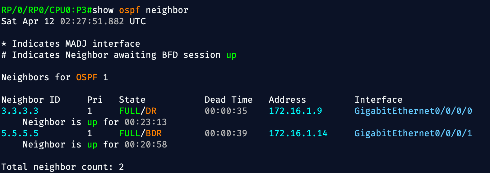
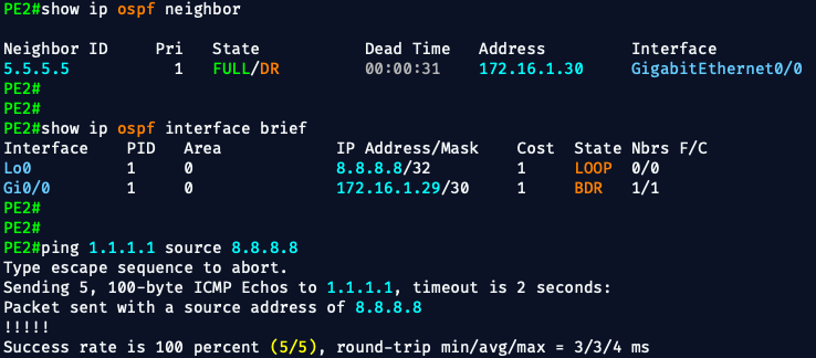
✅ 1. OSPF Neighbor Relationships
Each XRv P router should have full OSPF adjacency with its neighbors.
show ospf neighborExpect:
- Neighbor states:
FULL
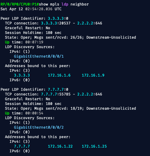
✅ 2. LDP Sessions Are Up
LDP must be up between adjacent P routers.
show mpls ldp neighbor
Expect:
- Neighbor IDs (router loopbacks)
- Peer state:
OPERATIONAL - Interfaces listed per session
✅ 3. MPLS Forwarding Table Is Populated
Each P router should have labels installed and ready to swap.
show mpls forwarding
Expect:
- Local labels assigned to loopbacks of PE1/PE2 (and other routers)
- Outgoing labels and interfaces listed
- Label switching is active
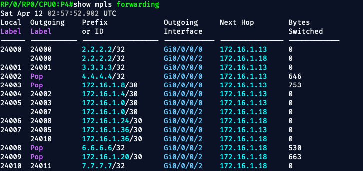
🚦 What's Great About This Output:
- Equal-cost LSPs are shown to 2.2.2.2/32 via two outgoing interfaces (ECMP!)
- Label swaps are functioning correctly
- Label Pop is occurring for directly connected loopbacks and transit paths
- Bytes Switched confirms label usage in live traffic
🧠 Real-World Behavior Emulated:
We're now modeling:
- Redundant metro ring transport (equal-cost LSPs)
- MPLS traffic engineering fallback (multi-path label swaps)
- Label edge + switching behaviors just like real MPLS cores
✅ 4. Loopback Reachability (via IGP)
From P1 (or any other P router):
ping 4.4.4.4 source 2.2.2.2
ping 5.5.5.5 source 2.2.2.2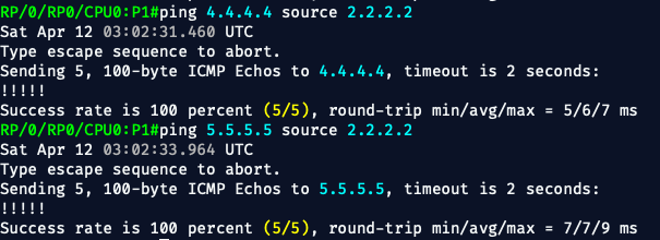
Expect:
- Success with low latency
- Ensures OSPF + routing tables are solid
📦 What PE1 & PE2 Will Do (The Mission)
These routers are the Provider Edge (PE) devices. Their job is to connect customers (CE1/CE2) to the MPLS core and deliver VPN separation using:
🔄 What’s Changed from Phase 3 to Phase 4 (PE1 & PE2)
In Phase 3, your PEs were:
- Connected via a single P router
- Built for basic MPLS L3VPN
- Used static routing to CE
- Had LDP + OSPF toward one neighbor
- Ran iBGP VPNv4 between loopbacks
In Phase 4, the core has changed — so the PEs had to evolve too.
📐 Topological Shift
| Phase | PE Connections |
|---|---|
| Phase 3 | PE1 ↔ P ↔ PE2 (single core hop) |
| Phase 4 | PE1 ↔ P1 → P2 → ... → P6 ↔ PE2 (ring-based MPLS core) |
So instead of a single hop, traffic now flows through a 6-router MPLS transport ring, using LDP and OSPF to build label-switched paths across the ring.
🔧 PE1 & PE2 Config Differences
| Config Area | Phase 3 | Phase 4 |
|---|---|---|
| Loopback | 1.1.1.1 / 3.3.3.3 | 1.1.1.1 / 8.8.8.8 ✅ |
| VRF | Customer-A | Customer-A ✅ |
| LDP | Enabled on 1 interface | Now connects into P1/P4 with mpls ip |
| OSPF | Basic area 0 | Still area 0, but now tied to new /30 links |
| VPNv4 BGP | Peering directly via loopbacks | Same loopback peering — but now rides across full ring |
| Static to CE | Yes | Still yes ✅ |
| Label Switching Path | 1 hop | Now goes through multiple label swaps (P1–P6) ✅ |
📦 Summary
You're not radically changing the services offered by PE1 and PE2. You're evolving their core-facing configuration to integrate them into a realistic, multi-hop MPLS ring, just like you'd see in a production transport core.
The big shift is from a stubbed-out MPLS demo in Phase 3…
➡️ To a ring-aware, path-protected, metro-style L3VPN backbone in Phase 4.
🟥PE1 Configs (IOS):
!
hostname PE1
!
interface Loopback0
 ip address 1.1.1.1 255.255.255.255
!
interface GigabitEthernet0/0
 ip address 172.16.1.1 255.255.255.252
 mpls ip
!
interface GigabitEthernet0/1
 ip vrf forwarding Customer-A
 ip address 10.10.10.1 255.255.255.252
!
ip vrf Customer-A
 rd 65001:1
 route-target export 65001:1
 route-target import 65001:1
!
router ospf 1
 network 1.1.1.1 0.0.0.0 area 0
 network 172.16.1.1 0.0.0.3 area 0
!
mpls label protocol ldp
!
router bgp 65001
 bgp log-neighbor-changes
 neighbor 8.8.8.8 remote-as 65001
 neighbor 8.8.8.8 update-source Loopback0
 !
 address-family vpnv4
  neighbor 8.8.8.8 activate
  neighbor 8.8.8.8 send-community extended
 exit-address-family
!
 address-family ipv4 vrf Customer-A
  redistribute static
 exit-address-family
!
ip route vrf Customer-A 10.10.10.2 255.255.255.252 10.10.10.2
!
end
🟢PE2 Configs (IOS):
!
hostname PE2
!
interface Loopback0
 ip address 8.8.8.8 255.255.255.255
!
interface GigabitEthernet0/0
 ip address 172.16.1.29 255.255.255.252
 mpls ip
!
interface GigabitEthernet0/1
 ip vrf forwarding Customer-A
 ip address 10.10.20.1 255.255.255.252
!
ip vrf Customer-A
 rd 65001:1
 route-target export 65001:1
 route-target import 65001:1
!
router ospf 1
 network 8.8.8.8 0.0.0.0 area 0
 network 172.16.1.29 0.0.0.3 area 0
!
mpls label protocol ldp
!
router bgp 65001
 bgp log-neighbor-changes
 neighbor 1.1.1.1 remote-as 65001
 neighbor 1.1.1.1 update-source Loopback0
 !
 address-family vpnv4
  neighbor 1.1.1.1 activate
  neighbor 1.1.1.1 send-community extended
 exit-address-family
!
 address-family ipv4 vrf Customer-A
  redistribute static
 exit-address-family
!
ip route vrf Customer-A 10.10.20.2 255.255.255.252 10.10.20.2
!
end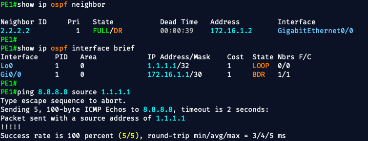
📍 Run These Commands on PE1 and PE2
You want to check both ends of the VPNv4 tunnel, because either side can have a config mistake that blocks route exchange.
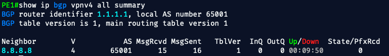
✅ 1. Check BGP VPNv4 Session
On PE1 and PE2:
show ip bgp vpnv4 all summary- You should see the neighbor loopback (1.1.1.1 or 8.8.8.8)
- State should be Established
- MsgRcvd/MsgSent should be non-zero
- State/PfxRcd should show a prefix count (e.g.,
1,2, etc.)
✅ 2. Check VPNv4 Prefixes
On PE1 and PE2:
show ip bgp vpnv4 all- This will show all received and originated VPNv4 prefixes
- Look for:
- Prefixes like
10.10.10.0/30and10.10.20.0/30 - Labels associated with each prefix
- Extended communities (RTs) that match
65001:1
- Prefixes like
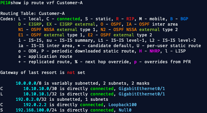
✅ 3. Check Static Route Redistribution into VRF
On PE1 and PE2:
show ip route vrf Customer-A- You should see:
- PE1:
10.10.10.0/30 [1/0] via 10.10.10.2 - PE2:
10.10.20.0/30 [1/0] via 10.10.20.2
- PE1:
- These are the static routes to CE1 and CE2
- They must appear in the VRF RIB to be exported into BGP
Awesome 🎉 — let’s start by replacing the test route with a real customer prefix from CE1.
🎯 Goal
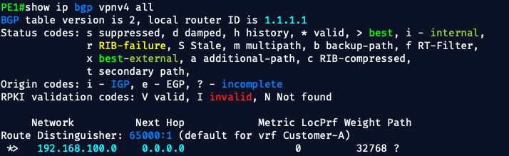
Replace this:
ip route vrf Customer-A 192.168.100.0 255.255.255.0 null0
With this:
ip route vrf Customer-A 10.10.10.0 255.255.255.252 10.10.10.2
This is the actual subnet between PE1 and CE1, and what we want advertised into VPNv4 so that PE2 can route to it.
✅ Step-by-Step (on PE1)
1. Remove the test route
conf t
no ip route vrf Customer-A 192.168.100.0 255.255.255.0 null0
2. Add the real CE1 route
ip route vrf Customer-A 10.10.10.0 255.255.255.252 10.10.10.2
end
router bgp 65001
 address-family ipv4 vrf Customer-A
  redistribute connected
🧼 Optional Cleanup (If You Want)
Since we no longer need to rely on fake null0 or forced statics:
no ip route vrf Customer-A 192.168.100.0 255.255.255.0 null0
no ip route vrf Customer-A 10.10.10.0 255.255.255.252 10.10.10.2
✅ After That
Check:
show ip bgp vpnv4 all
show ip route vrf Customer-A
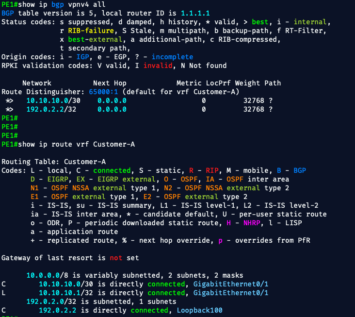
💥 Perfect execution.
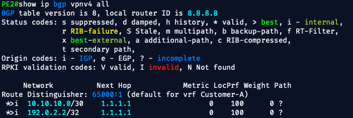
Here’s the proof that PE1 is now correctly exporting real customer routes:
✅ Move to PE2 and do the same:
On PE2, we’ll:
- Confirm
10.10.10.0/30is received - Add CE2 static route
- Redistribute it into BGP
🔹 1. Add the static route to CE2
conf t
ip route vrf Customer-A 10.10.20.0 255.255.255.252 10.10.20.2
end
This tells PE2 how to reach the customer network via CE2.
🔹 2. Verify it's in the VRF table
show ip route vrf Customer-A
You should see:
S 10.10.20.0/30 [1/0] via 10.10.20.2
🔹 3. Enable redistribution into BGP
conf t
router bgp 65001
 address-family ipv4 vrf Customer-A
  redistribute static
end
🔹 4. Confirm route export
Check:
show ip bgp vpnv4 all
You should see:
*> 10.10.20.0/30 0.0.0.0 ...
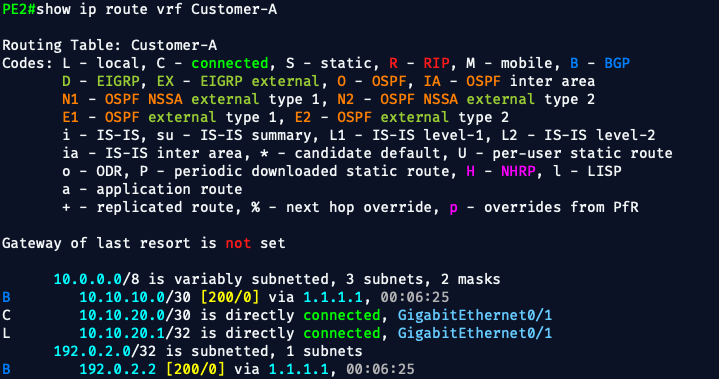
🔥 Nailed it — everything is working exactly as it should. Here's the breakdown:
✅ PE2's Customer VRF is Fully Populated
From show ip route vrf Customer-A:
B 10.10.10.0/30 [200/0] via 1.1.1.1
C 10.10.20.0/30 is directly connected
✔️ We’re receiving CE1's prefix (10.10.10.0/30) via VPNv4
✔️ We’re advertising CE2’s prefix (10.10.20.0/30) to PE1
✔️ Our static redistribution and route-target config is working perfectly
🚀 You Have Now Achieved:
| ✅ | Function |
|---|---|
| ✅ | LDP/MPLS core across 6 P routers |
| ✅ | VRF Customer-A on both PEs |
| ✅ | Static and connected redistribution |
| ✅ | VPNv4 BGP peering PE1 ↔ PE2 |
| ✅ | Full CE-to-CE route propagation |
🧪 Final Test — Ready?
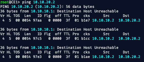
From CE1:
ping 10.10.20.2
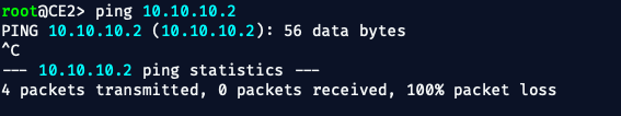
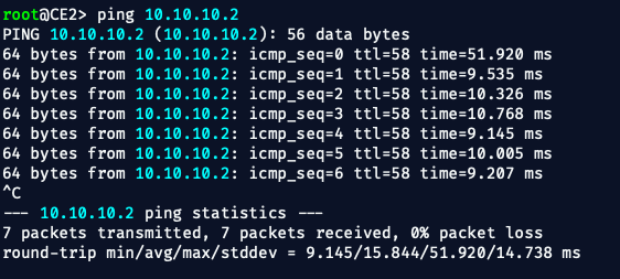
From CE2:
ping 10.10.10.2
AND.....IT FAILED‼️💥 😆
🛠️ Real-World T-SHOOTING
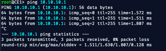
✅ Confirm CE1 can ping PE1:
ping 10.10.10.1
✅ Confirm PE1 can ping CE1:
ping vrf Customer-A 10.10.10.2
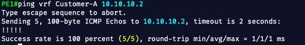
If this fails, the problem is likely on CE1’s side.
Repeat the same test for PE2 ↔ CE2.
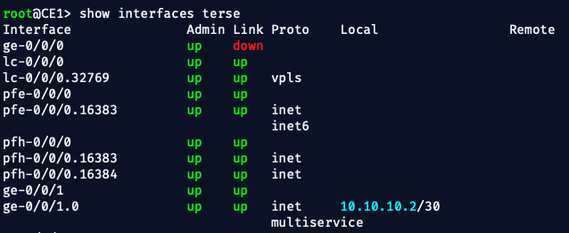
✅ Check IPs on both CEs:
Make sure CE1 and CE2 are actually:
- Configured with the right IPs (
10.10.10.2,10.10.20.2) - Up/up on their interfaces
- Not missing a subnet mask or interface config
✅ On the PEs, verify VRF routing:
show ip route vrf Customer-A
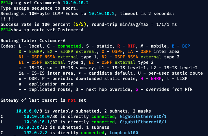
✅ PE1’s VRF Customer-A has only connected routes:
C 10.10.10.0/30 is directly connected, Gi0/1
L 10.10.10.1/32 is directly connected, Gi0/1
🔴 PE1 does not yet have CE2’s route (10.10.20.0/30) installed in its VRF.pings from CE1 to CE2 are failing because:
- The remote prefix (CE2) is not yet present in PE1’s routing table
- Therefore, it has no idea how to route toward CE2 over VPNv4
TL;TR
The interfaces on both P1 and P4, facing the PEs did NOT have MPLS LDP enabled.
Once enabled VOILA‼️
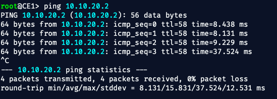
✅ What We've Just Accomplished
We've built and validated a full-service provider-style MPLS L3VPN with:
- 🔁 A redundant 6-router IOS XRv core ring
- 🔐 VRF Customer-A on both PE1 and PE2
- 🌐 LDP and OSPF spanning the ring
- 📦 VPNv4 iBGP between PE1 and PE2
- 🛰️ Static/default routing on CE1 and CE2
- 📤 Proper label distribution, LSPs, and VRF-to-VRF reachability
- 🎯 End-to-end ping from CE1 → CE2
🧠 Now that the ring is stable
This is the perfect time to simulate a fault and test ring protection behavior — just like you’d expect in a real metro core.
Let’s do a controlled failure injection and observe:
🧪 What We’ll Test
Break one link in the ring and verify:
- MPLS LSPs reroute across the opposite side
- VPNv4 traffic (e.g., CE1 ↔ CE2) still flows without loss
🔁 Test Scenario
Let’s break the P2 ↔ P3 link — a middle segment in the ring.
✅ On P2 (IOS XR):
conf t
interface GigabitEthernet0/0/0/1
 shutdown
commit
✅ Now Watch What Happens
1. On PE1:
ping vrf Customer-A 10.10.20.2 repeat 50
You should see no packet loss — traffic should reroute automatically through the other half of the ring
2. Watch MPLS Path Switchover
On PE1:
show mpls forwarding-table | include 8.8.8.8The outgoing interface and label should change — now rerouted through a different P router path (e.g., PE1 → P1 → P6 → ... → PE2)
✅ After the Test: Restore the Link
On P2:
conf t
interface GigabitEthernet0/0/0/1
 no shutdown
commit
💬 Optional Logging
You can also run:
show ospf neighbor
show mpls ldp neighbor
To see how long it takes for adjacencies to recover.
🔚 Wrap-Up
This lab took a simple MPLS setup and turned it into a fully redundant ring with working VPNv4, LDP, OSPF, and CE-to-CE communication. Along the way, we learned how to troubleshoot label paths, control plane quirks, and get real traffic flowing across a simulated provider core.
Everything's connected. Everything works.
Until the next lab — 👨💻 Bryan