Just Wanted Basic Connectivity — Here's What Actually Happened
Built a lab to test pings. Ended up debugging design. Turns out, not reaching the destination was exactly what was supposed to happen.

So, I started out just trying to build a simple network.
Nothing complicated —
some Linux nodes, a couple CE routers, a small core with a few PEs and Ps —
just enough to get basic end-to-end IP connectivity.
My goal was straightforward:
✅ Bring up the nodes.
✅ Get them talking across the network.
✅ Basic pings from Node1 to Node2, maybe Node1_2 to Node2.
That’s it.
At least, that’s what I thought was going to happen.
🛠️ The Lab Setup
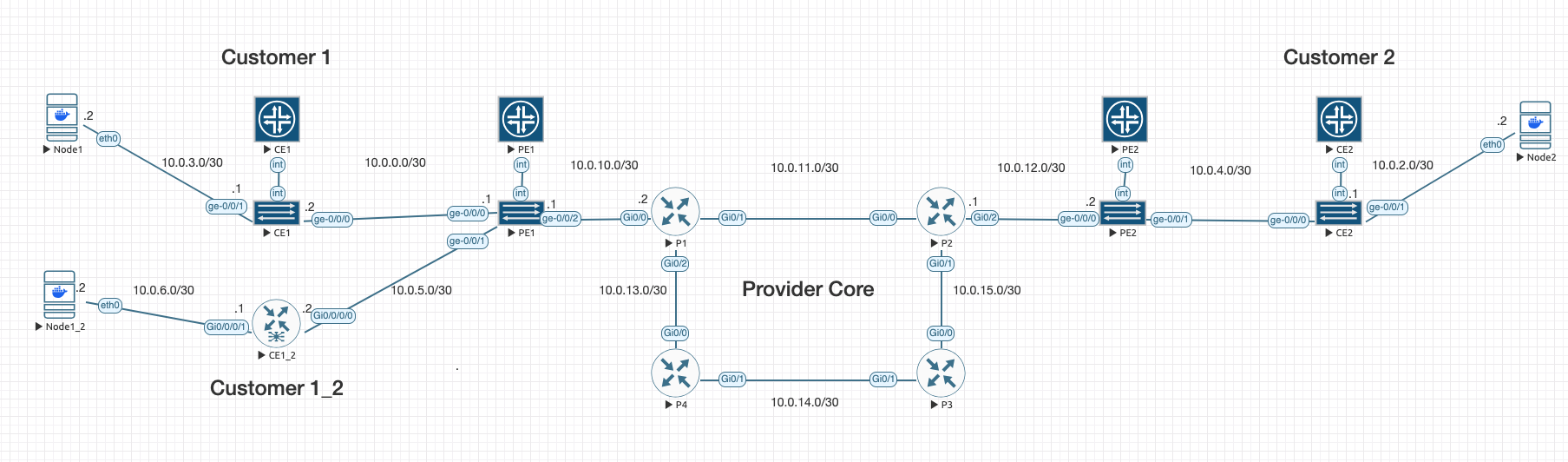
The topology started simple:
- Node1 ↔ CE1 ↔ PE1 ↔ P1 ↔ P2 ↔ PE2 ↔ CE2 ↔ Node2
- Node1_2 ↔ CE1_2 ↔ PE1
Each link had its own /30 subnet.
Each router had a loopback address.
I set up OSPF across the core.
Enabled MPLS forwarding.
Built LDP neighbor sessions between all core routers.
Before even getting to my original "tests,"
I already had full:
✅ OSPF neighbor adjacency
✅ Loopback-to-loopback IGP reachability
✅ LDP neighbors formed across the backbone
✅ MPLS label-switched paths between all routers
🎯 First Test: Pings
I spun up the nodes.
Set IP addresses and default routes on the Linux devices.
Built static routes on the CEs pointing upstream to the PEs.
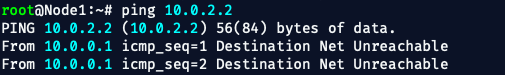
Fired off a ping from Node1 to Node2...
And immediately saw:
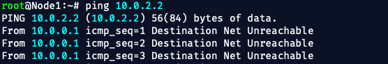
Ping from Node2 to Node1?
Same thing.
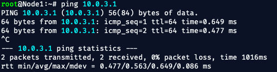
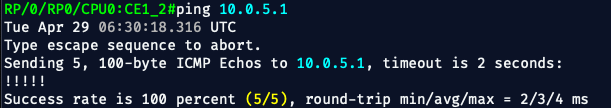
But when I pinged from a Node to its CE, or from the CE to its PE?
✅ Success.
When I tried pinging further?
❌ Nothing.
🧠 The Realization
At first, I thought something was broken.
Maybe a static route was missing.
Maybe OSPF wasn’t redistributing something.
But the more I looked, the more obvious it became:
✅ Every router in the core knew about the other routers' loopbacks.
✅ LDP sessions were up.
✅ Labels were installed.
✅ CEs could reach their directly connected PEs.
The problem wasn't the core.
The "problem" was design.
but hey, what's better than adding real stressors to your training?
You don’t learn resilience when everything goes right.
You learn it when you're tired, the pings aren’t answering,
and you have to dig in and figure out why —
or go to sleep. 💤
🚦 Why Nodes Couldn't Reach Each Other
In this setup:
- The Linux nodes are connected to CEs.
- CEs have static default routes pointing to PEs.
- PEs have static routes pointing toward their local CE-facing interfaces.
- The MPLS backbone is pure transport only — it doesn’t know about customer routes.
And that’s the whole point.
This lab didn't break.
It worked exactly how it's supposed to work at this stage.
In a real SP design, generally speaking:
- The core (P routers) only runs the provider’s internal IGP (like OSPF or IS-IS) and MPLS label switching.
- The core does not carry customer routes. Ever.
- PE routers are responsible for keeping track of customer prefixes — but they isolate those routes inside VRFs (Virtual Routing and Forwarding tables).
- Customer traffic moves across the backbone using labels, not IP lookups.
- iBGP (VPNv4 address family) is used between PE routers to exchange customer routes across the MPLS core.
- End-to-end customer reachability only exists once BGP/MPLS VPN services are layered on top of the MPLS transport — not before.
Without VRFs and VPNv4 BGP between PEs,
there's no way for PE1 to know "how" to reach Node2 sitting behind PE2.
📋 What Was Actually Working
✅ The Linux nodes could ping their directly connected CE router.
✅ CEs could ping the PE router they were attached to.
✅ Nodes could even ping the egress interface of the PE they connect to.
And that's good.
It proves:
- Static routing between the CEs and PEs was working.
- The PEs were reachable from their connected customers.
- The PEs were isolating the customer traffic exactly the way a real SP backbone should — no leaking into the core, no shortcuts.
The fact that the Nodes could ping up to the PE egress —
but couldn’t reach remote Nodes through the core —
was exactly the confirmation that the backbone was doing its job.
✅ Local reachability = Good.
✅ Global customer reachability = Not allowed yet (by design).
🚀 What's Next
Now that the transport core is up and running:
- I’ll build VRFs on PE1 and PE2.
- Bring up iBGP between PE1 and PE2 over their loopbacks.
- Exchange VPNv4 routes.
- Then finally deliver full Node1 ↔ Node2 reachability through the MPLS cloud.
That would be Phase 2.
But, like it always goes —
Now I’ve got multiple Phase 2s stacked up waiting to be done.
Every time I finish one thing, I end up starting something different —
another lab idea, another way to test something new, another rabbit hole to dive into.
Maybe at some point I’ll go back through and stitch a few of them together into one big Phase 2.
Maybe.
Either way — this foundation is ready for whatever comes next.

📑 Topology and Configs
As always, I am using EVE-NG and I have provided the base configs that I used.
🛠️ Here’s the Logic I Used at the Time:
| Layer | Behavior | Notes |
|---|---|---|
| Core P Routers (P1–P4) | OSPF for IGP + MPLS (LDP) | No customer routes! Only core transport |
| PE Routers (PE1/PE2) | OSPF toward core (P routers), MPLS enabled | CE-facing interfaces are NOT in OSPF |
| CE Routers (CE1, CE1_2, CE2) | Static route to PE, default route from PE | Real SP practice: CEs don't run IGP or MPLS |
| Hosts (Node1, Node1_2, Node2) | Static IP + default route to CE | Simple, basic hosts |
✅ MPLS labels ride across the core.
✅ CEs just do basic IP, no dynamic routing.
✅ Full control plane separation between customer and provider.
🌎 Loopback Assignments (Used for OSPF Router-ID and LDP)
| Device | Loopback IP |
|---|---|
| PE1 | 1.1.1.1/32 |
| P1 | 1.1.1.2/32 |
| P2 | 1.1.1.3/32 |
| P3 | 1.1.1.4/32 |
| P4 | 1.1.1.5/32 |
| PE2 | 1.1.1.6/32 |
PE1 (Juniper vMX)
set system host-name PE1
set interfaces lo0 unit 0 family inet address 1.1.1.1/32
set interfaces ge-0/0/0 unit 0 family inet address 10.0.0.1/30
set interfaces ge-0/0/1 unit 0 family inet address 10.0.5.1/30
set interfaces ge-0/0/2 unit 0 family inet address 10.0.10.1/30
set interfaces ge-0/0/2 unit 0 family mpls

set protocols ospf area 0.0.0.0 interface lo0.0
set protocols ospf area 0.0.0.0 interface ge-0/0/2.0

set protocols mpls interface ge-0/0/2.0
set protocols mpls interface lo0.0

set protocols ldp interface ge-0/0/2.0
set protocols ldp interface lo0.0


set routing-options static route 10.0.3.0/30 next-hop 10.0.0.2
set routing-options static route 10.0.6.0/30 next-hop 10.0.5.2
P1 (Cisco IOS)
hostname P1
!
interface Loopback0
 ip address 1.1.1.2 255.255.255.255
!
interface GigabitEthernet0/0
 description To PE1
 ip address 10.0.10.2 255.255.255.252
 mpls ip
 no shut
!
interface GigabitEthernet0/1
 description To P2
 ip address 10.0.11.1 255.255.255.252
 mpls ip
 no shut
!
interface GigabitEthernet0/2
 description To P4
 ip address 10.0.13.1 255.255.255.252
 mpls ip
 no shut
!
router ospf 1
 router-id 1.1.1.2
 network 10.0.10.0 0.0.0.3 area 0
 network 10.0.11.0 0.0.0.3 area 0
 network 10.0.13.0 0.0.0.3 area 0
 network 1.1.1.2 0.0.0.0 area 0
!
mpls ldp router-id Loopback0 force
mpls label protocol ldp
mpls ip
P2 (Cisco IOS)
hostname P2
!
interface Loopback0
 ip address 1.1.1.3 255.255.255.255
!
interface GigabitEthernet0/0
 description To P1
 ip address 10.0.11.2 255.255.255.252
 mpls ip
 no shut
!
interface GigabitEthernet0/1
 description To P3
 ip address 10.0.15.2 255.255.255.252
 mpls ip
 no shut
!
interface GigabitEthernet0/2
 description To PE2
 ip address 10.0.12.1 255.255.255.252
 mpls ip
 no shut
!
router ospf 1
 router-id 1.1.1.3
 network 10.0.11.0 0.0.0.3 area 0
 network 10.0.15.0 0.0.0.3 area 0
 network 10.0.12.0 0.0.0.3 area 0
 network 1.1.1.3 0.0.0.0 area 0
!
mpls ldp router-id Loopback0 force
mpls label protocol ldp
mpls ip
P3 (Cisco IOS)
hostname P3
!
interface Loopback0
 ip address 1.1.1.4 255.255.255.255
!
interface GigabitEthernet0/0
 description To P2
 ip address 10.0.15.1 255.255.255.252
 mpls ip
 no shut
!
interface GigabitEthernet0/1
 description To P4
 ip address 10.0.14.2 255.255.255.252
 mpls ip
 no shut
!
router ospf 1
 router-id 1.1.1.4
 network 10.0.15.0 0.0.0.3 area 0
 network 10.0.14.0 0.0.0.3 area 0
 network 1.1.1.4 0.0.0.0 area 0
!
mpls ldp router-id Loopback0 force
mpls label protocol ldp
mpls ip
P4 (Cisco IOS)
hostname P4
!
interface Loopback0
 ip address 1.1.1.5 255.255.255.255
!
interface GigabitEthernet0/0
 description To P1
 ip address 10.0.13.2 255.255.255.252
 mpls ip
 no shut
!
interface GigabitEthernet0/1
 description To P3
 ip address 10.0.14.1 255.255.255.252
 mpls ip
 no shut
!
router ospf 1
 router-id 1.1.1.5
 network 10.0.13.0 0.0.0.3 area 0
 network 10.0.14.0 0.0.0.3 area 0
 network 1.1.1.5 0.0.0.0 area 0
!
mpls ldp router-id Loopback0 force
mpls label protocol ldp
mpls ip
PE2 (Juniper vMX)
set system host-name PE2
set interfaces lo0 unit 0 family inet address 1.1.1.6/32
set interfaces ge-0/0/0 unit 0 family inet address 10.0.12.2/30
set interfaces ge-0/0/0 unit 0 family mpls
set interfaces ge-0/0/1 unit 0 family inet address 10.0.4.1/30

set protocols ospf area 0.0.0.0 interface lo0.0
set protocols ospf area 0.0.0.0 interface ge-0/0/0.0

set protocols mpls interface ge-0/0/0.0
set protocols mpls interface lo0.0

set protocols ldp interface ge-0/0/0.0
set protocols ldp interface lo0.0

set routing-options static route 10.0.2.0/30 next-hop 10.0.4.2
📦 CE Routers and Linux Hosts (Simple)
CE1, CE1_2, CE2:
- Static route to PE
- Default route from PE to CE
Node1, Node1_2, Node2:
- Static IP
- Default gateway to CE
CE1 (Juniper vMX)
set system host-name CE1
!
set interfaces ge-0/0/0 description "To PE1"
set interfaces ge-0/0/0 unit 0 family inet address 10.0.0.2/30
!
set interfaces ge-0/0/1 description "To Node1"
set interfaces ge-0/0/1 unit 0 family inet address 10.0.3.1/30
!
set routing-options static route 0.0.0.0/0 next-hop 10.0.0.1
CE1_2 (IOS-XR)
hostname CE1_2
!
interface GigabitEthernet0/0/0/0
 description To PE1
 ipv4 address 10.0.5.2 255.255.255.252
 no shutdown
!
interface GigabitEthernet0/0/0/1
 description To Node1_2
 ipv4 address 10.0.6.1 255.255.255.252
 no shutdown
!
router static
 address-family ipv4 unicast
  0.0.0.0/0 10.0.5.1
!
commit
CE2 (Juniper vMX)
set system host-name CE2
!
set interfaces ge-0/0/0 description "To PE2"
set interfaces ge-0/0/0 unit 0 family inet address 10.0.4.2/30
!
set interfaces ge-0/0/1 description "To Node2"
set interfaces ge-0/0/1 unit 0 family inet address 10.0.2.1/30
!
set routing-options static route 0.0.0.0/0 next-hop 10.0.4.1
Node1 (Linux)
ip addr flush dev eth0
ip addr add 10.0.3.2/30 dev eth0
ip link set eth0 up
ip route add default via 10.0.3.1
Node1_2 (Linux)
ip addr flush dev eth0
ip addr add 10.0.6.2/30 dev eth0
ip link set eth0 up
ip route add default via 10.0.6.1
Node2 (Linux)
ip addr flush dev eth0
ip addr add 10.0.2.2/30 dev eth0
ip link set eth0 up
ip route add default via 10.0.2.1
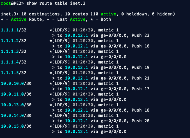
🎯 Connectivity Verification Checklist
Before I realized why the Nodes couldn’t reach each other,
I ran through some basic connectivity checks to make sure the core transport was actually working.
Here’s what I verified:
I'm not posting 20 different images of ping results. So, these images are only parts of the verification and in no particular order
✅ Node to CE Pings
✅ CE to PE Pings
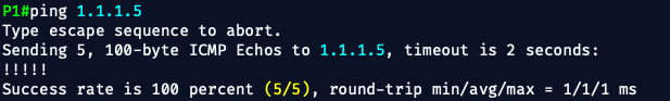
✅ PE to P Core Pings (loopbacks)
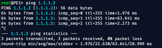
✅ P to P Core Pings
❌ Node to Node Pings
✅ OSPF Neighbors

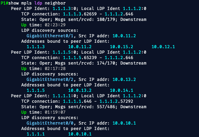
✅ LDP Neighbors
✅ MPLS Forwarding Table
🧱 Wrap-up
OK — I don't want to bore you with any more verifications and checks.
Everything that needs to work, works.
Everything that shouldn’t work (yet), doesn’t — and that’s the point.
What started as a quick lab to test "something" (I forgot now), turned into a solid foundation for a full MPLS-enabled Service Provider core.
Along the way, I ran into a few dead-ends, found clarity at 2AM,
and reminded myself that training under pressure (or exhaustion) just makes you sharper —
or forces you to go to sleep.💤
Now I’ve got a stack of Phase 2 labs I want to do.
Like I said earlier – maybe I’ll go back through and cleanly roll a few of them together in one big Phase 2.
Or maybe I’ll get distracted and start something else.
We’ll see.
But this core is done.
Thanks for reading —
catch you in the next one.
— Bryan ☮️ OUT!