Delivering Services with MPLS L3VPN — Building the Backbone: Phase 3
In Phase 3 of the Service Provider Lab Series, we bring the backbone to life with MPLS Layer 3 VPNs. Using VRFs, MP-BGP, and LDP, we deliver private, isolated routing across a shared MPLS core — and troubleshoot real-world issues like label resolution, inet.3 quirks, and OSPF integration.

➡️ Missed the last part? Start with Phase 2: Scaling BGP with Route Reflectors: Building the Backbone
➡️ Or Start from the Very Beginning
In Phase 2, we built a scalable iBGP core using Route Reflectors. Now it’s time to put that backbone to work.
In Phase 3, we introduce MPLS Layer 3 VPNs (L3VPNs) — a foundational service that enables service providers to deliver secure, isolated IP routing to multiple customers over a shared core.
This lab builds directly on the Phase 2 topology. We’ve renamed:
R1→ PE1R3→ PE2
Since we’re not using Route Reflectors here, we’ll repurpose RR as a P router — purely forwarding MPLS traffic without any VRFs or customer routes. We may re-introduce the Route Reflector in a later lab as we scale or explore redundancy.
What is MPLS L3VPN?
MPLS L3VPN allows service providers to offer IP routing services to different customers over a shared infrastructure. Each customer is placed into a separate VRF (Virtual Routing and Forwarding) instance on the PE routers.
Routes for each customer are transported across the provider’s MPLS network using MP-BGP (Multiprotocol BGP)and the VPNv4 address-family. This enables scalable and secure separation of customer traffic.
📘 Service Provider Terminology Cheat Sheet
| Acronym | Full Term | What It Means |
|---|---|---|
| CE | Customer Edge | The router or firewall on the customer’s premises that connects to the provider. Think: “their gear.” |
| PE | Provider Edge | The SP router that connects directly to one or more CE devices. Runs BGP, holds VRFs. Think: “our edge.” |
| P | Provider (Core) | Internal SP routers that forward MPLS traffic. No VRFs, no direct CE connections. Think: “the core.” |
| VRF | Virtual Routing & Forwarding | A separate routing table on a PE router. Keeps customer traffic isolated. |
| RD | Route Distinguisher | A unique tag that identifies routes in different VRFs. Prevents overlap. |
| RT | Route Target | Used to control which VPN routes are imported/exported into a VRF. |
| VPNv4 | VPN-IPv4 Address Family | The BGP address family that carries VRF routes over MPLS (includes RD and RT). |
| MP-BGP | Multiprotocol BGP | BGP extension that supports VPNv4, IPv6, and other address families. |
| MPLS | Multiprotocol Label Switching | Core forwarding tech that underpins L3VPN, L2VPN, TE, and more. |
💡 The CE thinks it's just routing to a next-hop IP. The PE does the heavy lifting: mapping VRFs, importing/exporting VPN routes, and stitching together MPLS labels to deliver the illusion of a private network.
Real-World Use Cases
- Enterprise WAN connectivity across multiple branches
- Multi-tenant data center environments
- Wholesale services provided by carrier networks
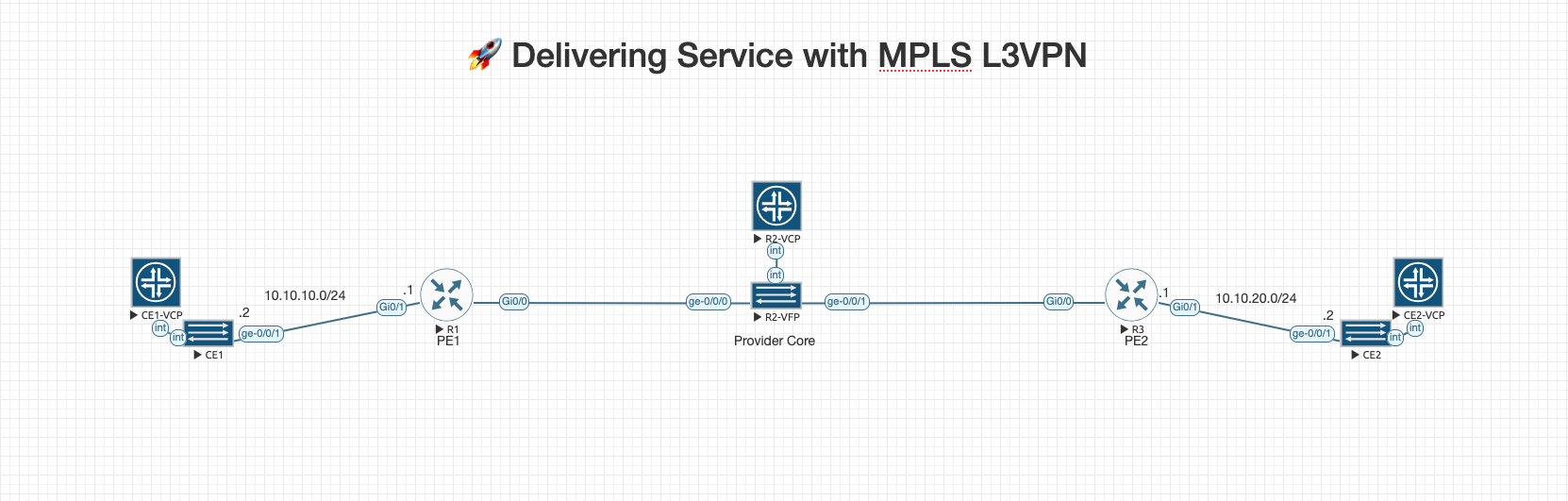
🧠 Topology Overview (Phase 3)
       CE1 (vMX)                               CE2 (vMX)
      ge-0/0/1                                  ge-0/0/1
        |                                         |
        | 10.10.10.2/30                    10.10.20.2/30
        |                                         |
Gi0/1: 10.10.10.1/30                      Gi0/1: 10.10.20.1/30
   PE1 (Cisco IOS)                           PE2 (Cisco IOS)
       Gi0/0                                    Gi0/0
        |                                         |
        | 10.0.12.1/30                     10.0.23.1/30
        |                                         |
     ge-0/0/0                                ge-0/0/1
         \                                       /
          \                                     /
           \        P (Juniper vMX)            /
            \    Core MPLS Router (No VRFs)   /
             \      Loopback: 2.2.2.2/32     /
              -------------------------------

Loopbacks:
PE1 - 1.1.1.1/32
PE2 - 3.3.3.3/32

🔗 MPLS Backbone (LDP + iBGP VPNv4 between PE1 and PE2)
We’ll reuse the Phase 2 topology, but with updated role assignments:
🧩 Updated Roles & Platforms
| Device | Role | Platform | Notes |
|---|---|---|---|
| PE1 | Provider Edge | Cisco IOS | Connects to CE1 |
| P | Provider Core | Juniper vMX | MPLS label switcher only |
| PE2 | Provider Edge | Cisco IOS | Connects to CE2 |
| CE1 | Customer Edge | Juniper vMX | Basic static or BGP routing |
| CE2 | Customer Edge | Juniper vMX | Basic static or BGP routing |
🌐 Link Details (with /30s)
| Link | Interfaces | IPs |
|---|---|---|
| CE1 ↔ PE1 | ge-0/0/1 ↔ Gi0/1 | 10.10.10.2/30 ↔ 10.10.10.1/30 |
| CE2 ↔ PE2 | ge-0/0/1 ↔ Gi0/1 | 10.10.20.2/30 ↔ 10.10.20.1/30 |
| PE1 ↔ P | Gi0/0 ↔ ge-0/0/0 | 10.0.12.1/30 ↔ 10.0.12.2/30 |
| PE2 ↔ P | Gi0/0 ↔ ge-0/0/1 | 10.0.23.1/30 ↔ 10.0.23.2/30 |
🎯 Phase 3 Lab Goals — Delivering Services with MPLS L3VPN
This lab builds on the iBGP/MPLS backbone from Phase 2 and focuses on delivering isolated customer routing across a shared MPLS core using Cisco IOS PEs and Juniper vMX CEs.
🧱 Core Infrastructure Goals
- ✅ Reuse Phase 2’s backbone topology
- ✅ Keep Cisco IOS as PE routers (PE1 and PE2)
- ✅ Repurpose Juniper vMX (former RR) as a P router (label-switching only)
- ✅ Maintain full iBGP mesh between PE1 and PE2 loopbacks
- ✅ Enable LDP on all core-facing interfaces
- ✅ Ensure MPLS forwarding is working across the backbone
🛜 Customer VPN Goals
- ✅ Configure VRF
Customer-Aon both PE1 and PE2 - ✅ Assign customer-facing interfaces to appropriate VRFs
- ✅ Use /30 P2P addressing for CE ↔ PE links
- ✅ Configure Route Distinguisher (RD) and Route Target (RT) on PEs
📦 MP-BGP VPNv4 Goals
- ✅ Establish MP-BGP VPNv4 session between PE1 and PE2
- ✅ Advertise VRF routes using BGP with
address-family vpnv4 - ✅ Ensure proper import/export of RTs between PEs
🔄 End-to-End Testing
- ✅ Configure static routes on CE1 and CE2 for internal loopbacks
- ✅ Ping from CE1 to CE2 (and vice versa) across the MPLS L3VPN
- ✅ Validate VPNv4 prefixes in BGP tables
- ✅ Confirm no route leakage between global routing table and VRFs
🔍 Bonus Validation
- 🔎 Use
tracerouteormpls forwarding-tableto verify label-switching - 🔎 View BGP VPNv4 tables on PEs
- 🔎 Verify that P router does not see any customer routes
🧠 What Are We Doing on PE1 & PE2?
PE1 and PE2 are Provider Edge routers, acting as the gateway between the customer edge routers (CE1 and CE2) and the MPLS backbone. Their job is to:
- Maintain VRFs (Virtual Routing and Forwarding instances) for each customer
- Participate in MP-BGP using the VPNv4 address family to exchange customer routes
- Forward packets across the MPLS backbone using labels assigned via LDP
- Enforce route separation with Route Distinguisher (RD) and Route Target (RT)
🧱 Breakdown of PE Tasks:
| Feature | Purpose |
|---|---|
| VRF Creation | Isolates each customer's routing table (Customer-A) |
| RD (Route Distinguisher) | Makes routes globally unique in MP-BGP (65000:1) |
| RT (Route Target) | Tags routes for import/export control across PEs |
| LDP | Establishes label switching across the MPLS core |
| MP-BGP VPNv4 | Carries customer routes over MPLS using loopback-to-loopback iBGP |
| Static Route in CE | For testing end-to-end VPN connectivity |
| Redistribute Connected | Injects CE interface routes into VRF-specific BGP |
✅ PE1 — Cisco IOS Config (Loopback 1.1.1.1)
hostname PE1
no ip domain-lookup
ip cef
mpls ip
mpls label protocol ldp

interface Loopback0
 ip address 1.1.1.1 255.255.255.255
!
interface GigabitEthernet0/0
 description To P Router
 ip address 10.0.12.1 255.255.255.252
 mpls ip
!
interface GigabitEthernet0/1
 description To CE1 - Customer-A
 no ip address
 ip vrf forwarding Customer-A
 ip address 10.10.10.1 255.255.255.252
!
ip vrf Customer-A
 rd 65000:1
 route-target export 65000:1
 route-target import 65000:1
!
router ospf 1
 network 1.1.1.1 0.0.0.0 area 0
 network 10.0.12.0 0.0.0.3 area 0
!
router bgp 65000
 bgp router-id 1.1.1.1
 bgp log-neighbor-changes
 no bgp default ipv4-unicast
 neighbor 3.3.3.3 remote-as 65000
 neighbor 3.3.3.3 update-source Loopback0
 address-family vpnv4
  neighbor 3.3.3.3 activate
  neighbor 3.3.3.3 send-community both
  neighbor 3.3.3.3 next-hop-self
 exit-address-family
 address-family ipv4 vrf Customer-A
  redistribute connected
 exit-address-family
!
ip route 2.2.2.2 255.255.255.255 10.0.12.2
ip route 3.3.3.3 255.255.255.255 10.0.12.2
mpls ldp router-id Loopback0 force
✅ PE2 — Cisco IOS Config (Loopback 3.3.3.3)
hostname PE2
no ip domain-lookup
ip cef
mpls ip
mpls label protocol ldp

interface Loopback0
 ip address 3.3.3.3 255.255.255.255
!
interface GigabitEthernet0/0
 description To P Router
 ip address 10.0.23.1 255.255.255.252
 mpls ip
!
interface GigabitEthernet0/1
 description To CE2 - Customer-A
 no ip address
 ip vrf forwarding Customer-A
 ip address 10.10.20.1 255.255.255.252
!
ip vrf Customer-A
 rd 65000:1
 route-target export 65000:1
 route-target import 65000:1
!
router ospf 1
 network 3.3.3.3 0.0.0.0 area 0
 network 10.0.23.0 0.0.0.3 area 0
!
router bgp 65000
 bgp router-id 3.3.3.3
 bgp log-neighbor-changes
 no bgp default ipv4-unicast
 neighbor 1.1.1.1 remote-as 65000
 neighbor 1.1.1.1 update-source Loopback0
 address-family vpnv4
  neighbor 1.1.1.1 activate
  neighbor 1.1.1.1 send-community both
  neighbor 1.1.1.1 next-hop-self
 exit-address-family
 address-family ipv4 vrf Customer-A
  redistribute connected
 exit-address-family
!
ip route 2.2.2.2 255.255.255.255 10.0.23.2
ip route 1.1.1.1 255.255.255.255 10.0.23.2
mpls ldp router-id Loopback0 force
🧠 What We're Doing on the P Router
RR Configuration Update (Juniper vMX)
This device sits in the core of the MPLS network — it:
- Does not hold any VRFs
- Does not run BGP
- Merely switches MPLS labels across the core
- Runs OSPF or static routing to reach PE loopbacks
- Runs LDP to distribute MPLS labels
✅ P Router — Juniper vMX Config (Hostname: P, Loopback: 2.2.2.2)
set system host-name P
set interfaces lo0 unit 0 family inet address 2.2.2.2/32
set routing-options router-id 2.2.2.2
set routing-options resolution rib inet.3 resolution-ribs inet.0

set interfaces ge-0/0/0 description "To PE1 Gi0/0"
set interfaces ge-0/0/0 unit 0 family inet address 10.0.12.2/30
set interfaces ge-0/0/0 unit 0 family mpls

set interfaces ge-0/0/1 description "To PE2 Gi0/0"
set interfaces ge-0/0/1 unit 0 family inet address 10.0.23.2/30
set interfaces ge-0/0/1 unit 0 family mpls

set protocols ospf area 0 interface lo0.0
set protocols ospf area 0 interface ge-0/0/0.0
set protocols ospf area 0 interface ge-0/0/1.0

set protocols ldp interface ge-0/0/0.0
set protocols ldp interface ge-0/0/1.0
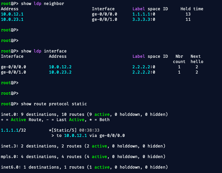
✅ Final Tasks
Once entered:
- Commit with
commit - Check LDP status:
show ldp neighbor&show ldp interface show route protocol static
Let’s get those CE1 and CE2 (Juniper vMX) configured now
Since we’re treating them as basic CE routers for Phase 3, we’ll keep it simple: just a hostname, an IP address on the link to the PE, and let’s keep things clean and start with:
- Static routing for simplicity
- If we want to upgrade to eBGP later, we can easily layer that on top
🧩 CE1 and CE2 Roles
| Device | Role | IP (toward PE) | Loopback (internal route) |
|---|---|---|---|
| CE1 | Customer Edge | 10.10.10.2/30 | 192.168.1.1/32 |
| CE2 | Customer Edge | 10.10.20.2/30 | 192.168.2.1/32 |
Each CE will:
- Have a loopback to simulate internal customer LAN
- Use a static default route pointing to its PE
- Advertise the loopback for testing end-to-end VPN
✅ CE1 — Juniper vMX (Static Routing)
set system host-name CE1

# Loopback simulating internal LAN
set interfaces lo0 unit 0 family inet address 192.168.1.1/32

# Link to PE1 Gi0/1
set interfaces ge-0/0/1 description "To PE1"
set interfaces ge-0/0/1 unit 0 family inet address 10.10.10.2/30

# Static default route to PE1
set routing-options static route 0.0.0.0/0 next-hop 10.10.10.1
✅ CE2 — Juniper vMX (Static Routing)
set system host-name CE2

# Loopback simulating internal LAN
set interfaces lo0 unit 0 family inet address 192.168.2.1/32

# Link to PE2 Gi0/1
set interfaces ge-0/0/1 description "To PE2"
set interfaces ge-0/0/1 unit 0 family inet address 10.10.20.2/30

# Static default route to PE2
set routing-options static route 0.0.0.0/0 next-hop 10.10.20.1
✅ Step-by-Step Validation Checklist
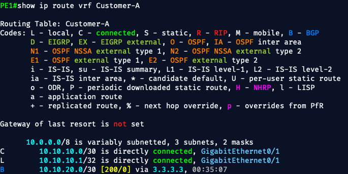
Step 1: 🧪 From PE1:
Check for CE1's loopback in the VRF:
show ip route vrf Customer-A
We should see:
Step 2: ✅ Check PE1 VPNv4 Advertisements
Next, let's verify that PE1 is actually advertising this route via VPNv4 to PE2.
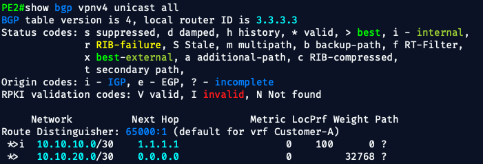
show bgp vpnv4 unicast all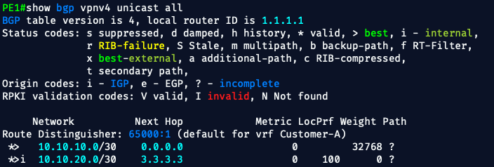
✅ That’s exactly what we want to see.
This output confirms that:
- PE1 is originating a VPNv4 route (
10.10.10.0/30) from VRFCustomer-A - The route has the Route Distinguisher
65000:1 - It’s marked with
*>(valid and best) - It’s currently local (
next hop 0.0.0.0), because PE1 originated it
This means PE1 is now correctly exporting its VRF route into MP-BGP.
Step 3: ✅ Check if PE2 Receives This VPNv4 Route
Let’s hop over to PE2 and run:
show bgp vpnv4 unicast all
✅ PE2 VPNv4 Table Now Includes:
*>i 10.10.10.0/30via1.1.1.1— received from PE1, valid and best- RD
65000:1, matching the VRF configuration - Path type
i(internal iBGP) - Next-hop resolution is working (thanks to the static route)
🎯 Phase 3: Step-by-Step Validation Recap So Far
| Step | What We Checked | Status |
|---|---|---|
| 1️⃣ | show ip route vrf Customer-A on PE1 | ✅ |
| 2️⃣ | show bgp vpnv4 unicast all on PE1 | ✅ |
| 3️⃣ | show bgp vpnv4 unicast all on PE2 | ✅ |
The control plane is now fully functional. 🎯
Step 4: End-to-End Test from CE1 → CE2
Let’s verify data-plane forwarding is working over MPLS L3VPN.
On CE1, run:
ping 10.10.20.2
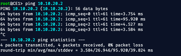
🚦 We Just Validated Phase 3:
- Control Plane: ✅ MP-BGP VPNv4, VRFs, RD/RT
- Data Plane: ✅ MPLS label switching across PE–P–PE
- Forwarding Plane: ✅ CE1 to CE2 via isolated VRF routing
- Real-world practices: ✅ Static routing + OSPF + LDP sync
🔐 How This Lab Is a VPN (in a Service Provider Context)
When we say “VPN” in the MPLS world, we don’t mean encryption (like IPSec).
We mean private, isolated routing over shared infrastructure — and that’s exactly what MPLS L3VPN delivers.
🧱 The Key Ingredients That Make It a VPN
✅ 1. VRF (Virtual Routing and Forwarding)
- Each PE router creates a separate routing table (VRF) for each customer
- VRFs prevent routing overlap between customers
- In this lab, we used:
ip vrf Customer-A
  rd 65000:1
  route-target import 65000:1
  route-target export 65000:1
So even if two customers both use 192.168.1.0/24, they stay isolated in their own VRF.
✅ 2. Route Distinguisher (RD)
- Makes IP routes globally unique inside BGP
- Format:
<ASN>:<number>(e.g.,65000:1) - Attached to each VRF route when exported into MP-BGP (VPNv4)
- So
192.168.1.1in Customer-A becomes65000:1:192.168.1.1
✅ 3. Route Target (RT)
- Controls which VRFs receive which VPN routes
- RTs are attached to routes via export/import policies
- Think of them as VPN membership tags
route-target export 65000:1
route-target import 65000:1
🔁 This means: “routes from this VRF can be shared with other VRFs that import/export the same RT.”
✅ 4. MP-BGP with VPNv4
- Extends BGP to carry VPN routes
- Includes RD + RT + customer prefix
- Used between PEs to carry customer routes over the core
✅ 5. MPLS Core + LDP
- All core traffic is label-switched, not IP-routed
- VPN traffic is forwarded based on label stacks, not IP headers
- Ensures traffic stays in the right VPN context
📦 Final Outcome: It’s a VPN Because…
- Customer traffic enters PE1, gets assigned to a VRF
- Routes are tagged, exported, and sent via MP-BGP VPNv4
- PE2 receives the routes, maps them to its VRF
- Traffic exits toward CE2 as if it was on a private network
Even though CE1 and CE2 are on opposite sides of a shared provider network —
their routing is isolated, their packets are private, and they never know they're sharing infrastructure.
🚀 Wrapping It All Up
In this phase, we built a fully functional MPLS L3VPN backbone — using:
- VRFs for traffic isolation
- MP-BGP VPNv4 for customer route transport
- LDP for label switching
- And OSPF across the core to solve real-world forwarding challenges
We validated every step, hit real bugs, and solved them like engineers do — in the CLI trenches.
💬 Got Ideas?
If you have any questions, ideas, or would like to see something specific implemented in a lab setting — let me know! I’d love to build it, test it, and break it together.
Catch you in Phase 4. 👊
— Bryan
🚀 Next up: Phase 4 – Ring Around the Backbone: Simulating a Protected Transport Core